Marble Pump Kit Assembly Instructions
Introduction
The Marble Pump 3.0 is finally here, with numerous design improvements and refinements to make this the very best TrackStacker Marble Pump till date! If you want to build a Marble Pump for yourself, please make sure to thoroughly read the information on this page and please do not hesitate to ask any questions you may have in the TrackStacker Discord community. The Marble Pump is certainly the most challenging Track to fabricate till date, and has many assembly steps including soldering and wiring. It will be beneficial to have already fabricated a few other Tracks before embarking on a Marble Pump build - being familiar with TrackStacker magnetic polarization standards is helpful for this build.
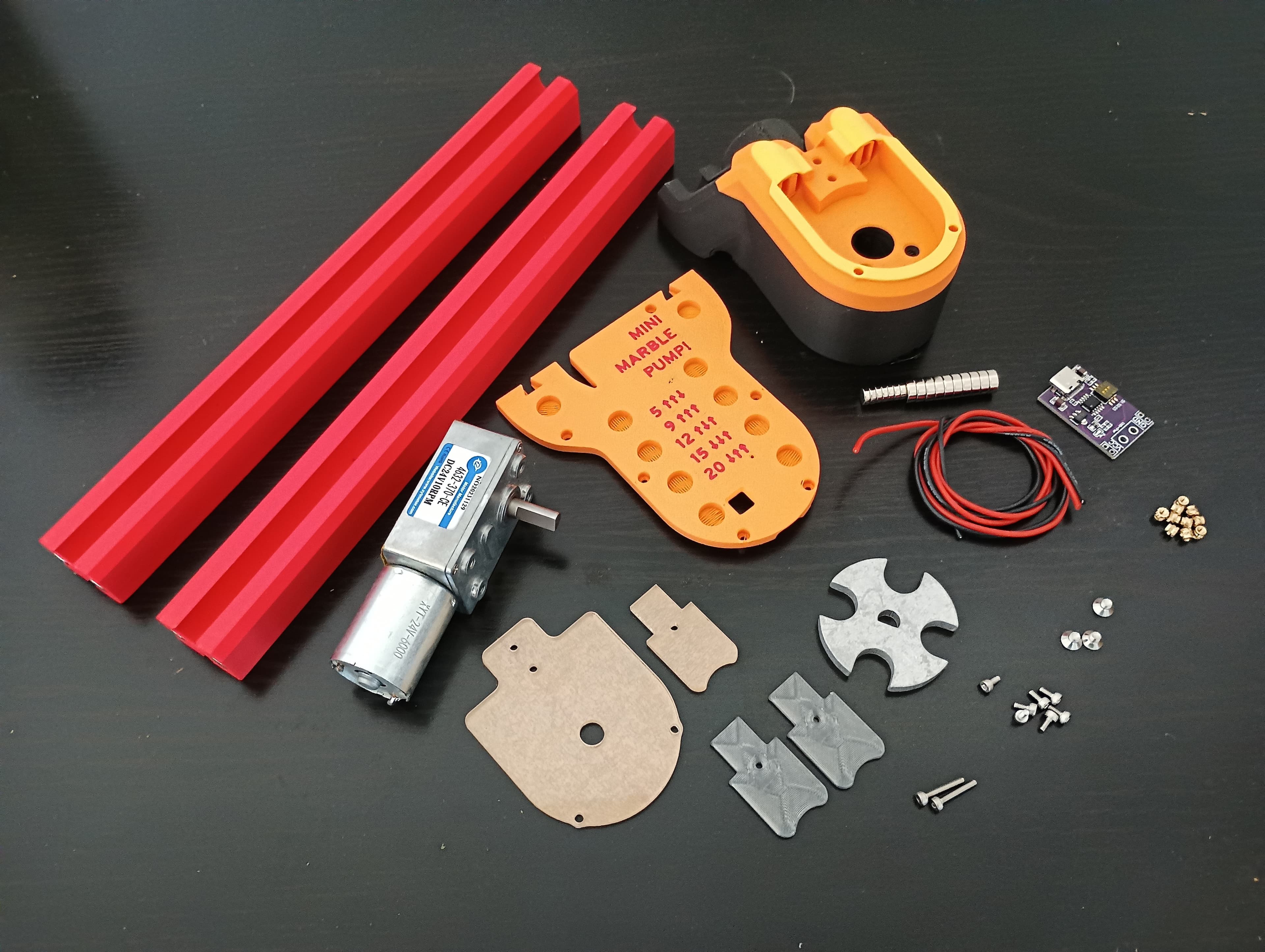
Bill of Materials
-
1x DC Gear Motor
The beating heart of the Marble Pump is the JGY370 right angle DC worm gearmotor. The Marble Pump has been designed and tested around a motor rated for 24V / 10RPM. However, slower and faster motors could be used to achieve different pump performance characteristics. There are a large variety of voltages and RPMs avaialble in this form factor.
-
1x DPDT (on-off-on) Toggle Switch
This 3-position DPDT toggle switch (MTS-203) will act as the entire direction control system for the pump. Wired in an H-Bridge configuration allows bi-directional motor control, as well as Pump On/Off when using a 3-position DPDT switch as specified.
-
1x USB C PD Trigger PCB
This little PCB lets you select what voltage you want to run your Pump at from the available voltages your USB-C PD power supply provides. To get maximum pump speed, you will need a USB-C PD (Power Delivery) charger that can provide upto 20V. This PCB negotiates with your PD power supply to deliver the voltage you want to your Pump. You can use the DIP switches onboard to actually set the Pump voltage.
-
Wire
You will need approximately 400mm of 18-20AWG 2-core zip cord for wiring up your Marble Pump.
-
Heat Shrink Tubing
You will need approximately 50mm of heat shrink tubing to insulate the soldered terminals of your motor and switch.
-
1x Pump Wheel - Laser Cut 4mm Aluminum
-
1x Pump Ramp - Laser Cut 3mm Acrylic
-
9x M2 Heat Set Inserts
-
6x M2x4mm Socket Head Cap Screws
-
4x ⌀6mm ↧2mm Neodymium Magnets
-
6x ⌀8mm ↧3mm Neodymium Magnets
Printed Parts
-
1x Pump Body - Printed in PLA
-
1x Ramp Spacer - Printed in Polycarbonate
-
1x Pump Back - Printed in PLA
Notes on Material Selection
The Marble Pump is a high-performance Track that needs to be constructed using a particular set of materials for optimum performance. Some of these may be tricky to source for the DIY Track Fabricator, so I have listed some options for substitutions below.
Pump Wheel
The Pump Wheel is the single most critical part to the proper functioning of your Marble Pump. This part is responsible for transmitting the torque from the motor into a force that can lift an upward stream of Marbles. As a result, this part is actually subjected to very high strains and forces and must be fabricated from a material capable of withstanding this kind of abuse.
All Marble Pumps made and sold by TrackStacker Labs use an aluminum Pump Wheel laser cut from 5052 H32 Aluminum that is 4.75mm or 0.187" thick. If you do not have access to a laser cutter capable of cutting aluminum that thick, consider using a service like SendCutSend to have your Pump wheels laser cut for you. If you cannot find a service like this where you live, you can alternatively 3D print a Pump Wheel out of Polycarbonate filament.
Warning
Please be warned however that using a 3D-printed Pump Wheel will result in a Pump with much reduced durability and as such the maximum reccomended height of lift will be reduced by about 30% compared to metal pump wheels. I have experimented heavily with different types of material and print settings, all of which have failed to provide a Pump Wheel adequately strong to meet the design standards of the Marble Pump. If you MUST print a Pump Wheel, please do so in Polycarbonate filament with maximum walls.
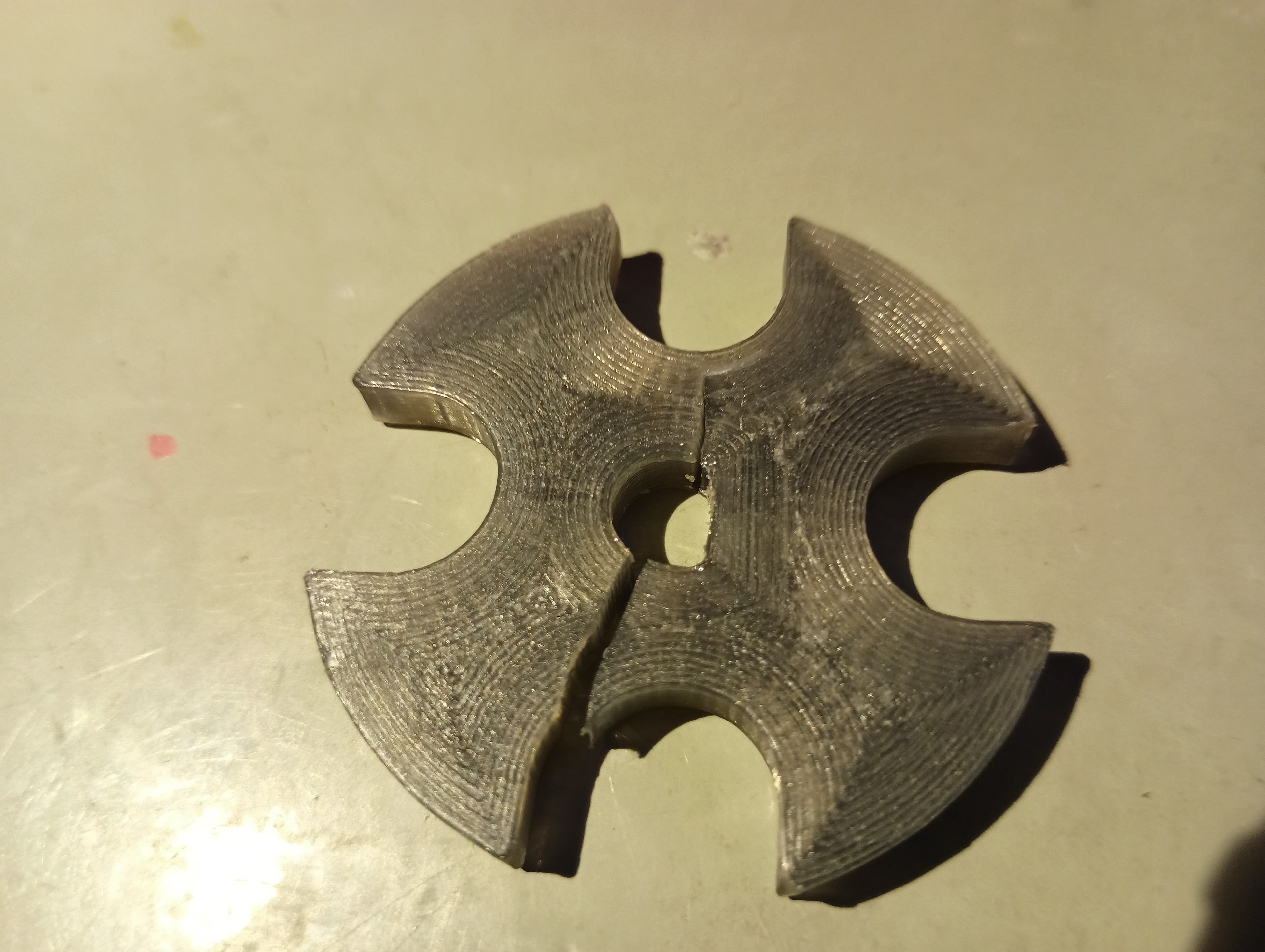
Shown above is my most durable Polycarbonate Pump Wheel till date, which ultimately fractured along the D shaft after a hundred or so lifting hours of testing.
Danger
A PUMP WHEEL PRINTED IN PLA WITLL BE ESSENTIALLY UNUSABLE!
Feed Ramp
The Feed Ramp is another critical motion component that restricts the motion of the Marbles upwards into the lifted stream. It will see wear over time, and hence needs to be made from a more durable material than PLA. Ideally, it should be made from 3D printed Polycarbonate or laser cut acrylic. Either of these methods will yeild Feed Ramps that will last over 250+ lifting hours.
Cover Plate
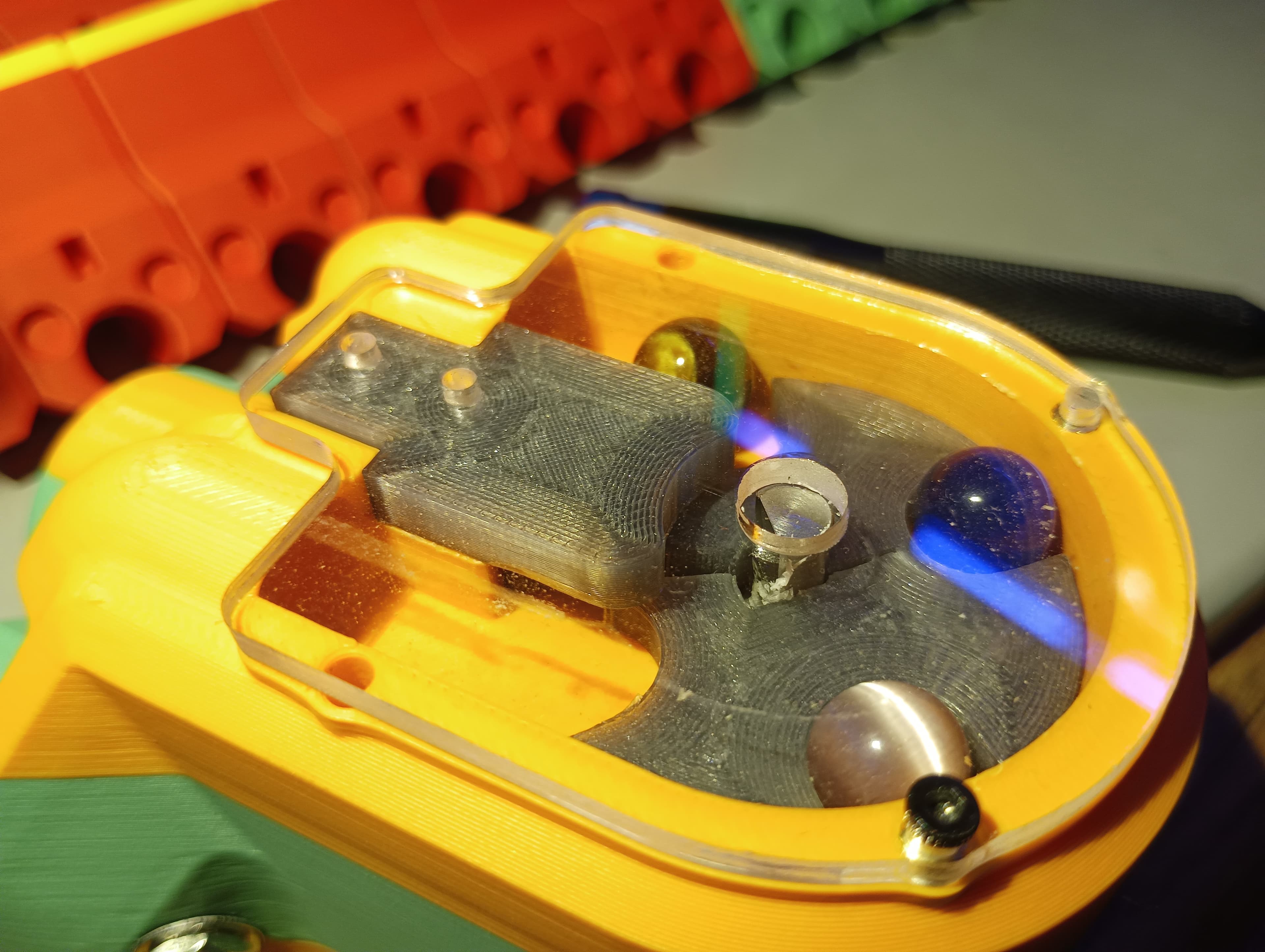
The Cover Plate for the Marble Pump should ideally be made out of laser cut 3mm or 1/8" thick acrylic. You can always use a thicker acrylic if that is what you have on hand. Since the weight of the lifted Stack of Marbles exterts a downward pressure on the cover plate, it is reccommended to stick to 3mm+ thickness to prevent any bending or warping of the cover plate. Also using laser cut acrylic has the benefit of being transparent and allowing you to look at the hypnotic movement of marbles through the Pump!
However, if you do not have access to a laser cutter, you can 3D print a Cover Plate for your Pump using PETG or Polycarbonate. Shown below is a 3D printed Cover Plate in PC with gyroid infill and no top layers. This allows you to somewhat makeout the movement of marbles within the Pump, and gives a cool finish.
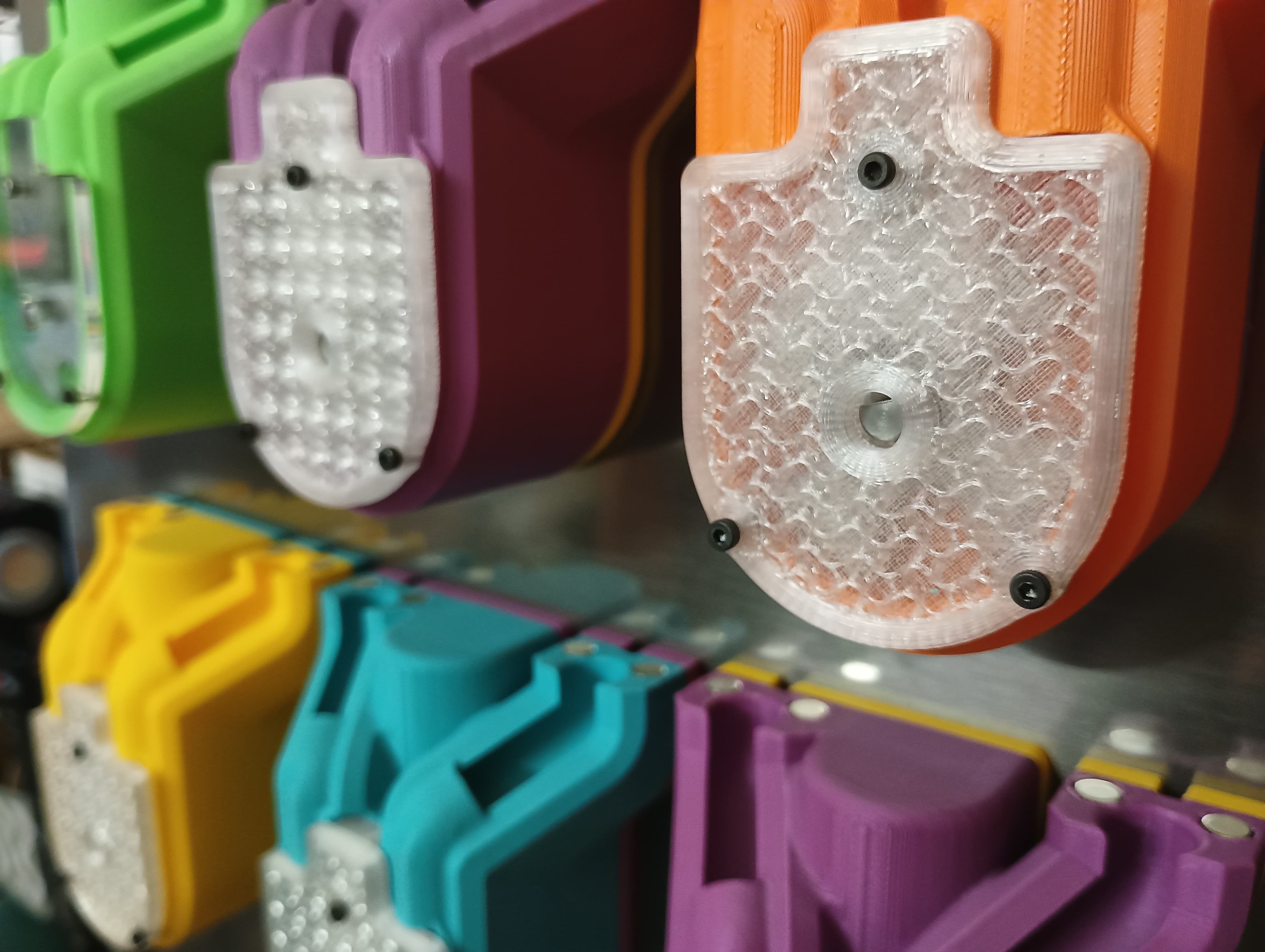
(Left) - clear, laser cut 3mm acrylic cover plate (Right) - 3D printed gyroid cover plate in Polycarbonate
Slicer Settings
Unlike most other Tracks, The Marble Pump needs very particular settings in order to print successfully, and this is mainly for two reasons -
- The Pump Body needs quite a lot of support in order to print correctly.
- The Pump Wheel (if you are printing it) needs to be sliced for maximum strength and durability.
Supports
I reccomend printing your Pump Body with Normal supports in snug mode, with a threshold angle of 40 degrees. Slicers these days are capable of generating generally very easy to remove support material, but your milage may vary based on the specific filament that you are using.
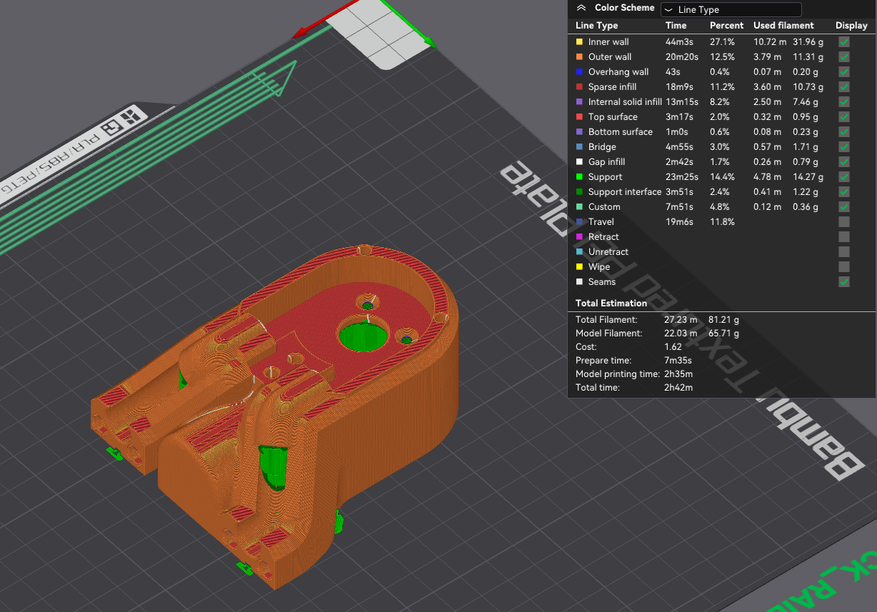
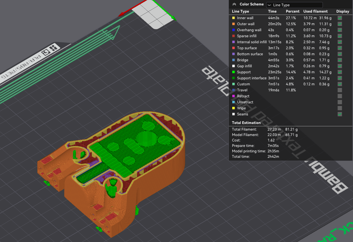
This is what your supports should look like in your slicer. Support material shown in green.
This is what a properly supported Pump body actually should look like - as you can see in the images below, my support settings are tuned so nicely that the whole block of supports stayed attached to the build plate while the part released effortlessly. This Pump Body has been printed in Plum BambuLab PLA Matte, and turned out with a lovely surface finish and clean support removal without much fuss.
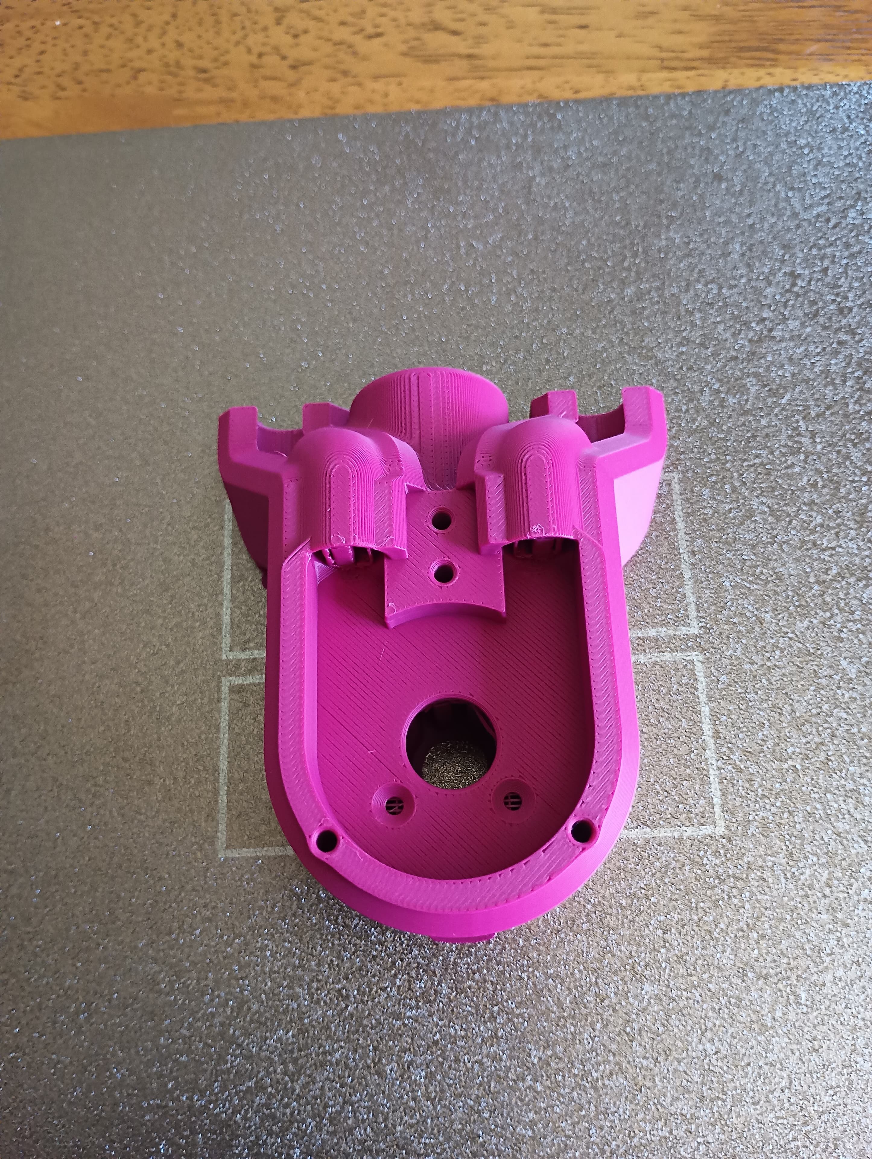
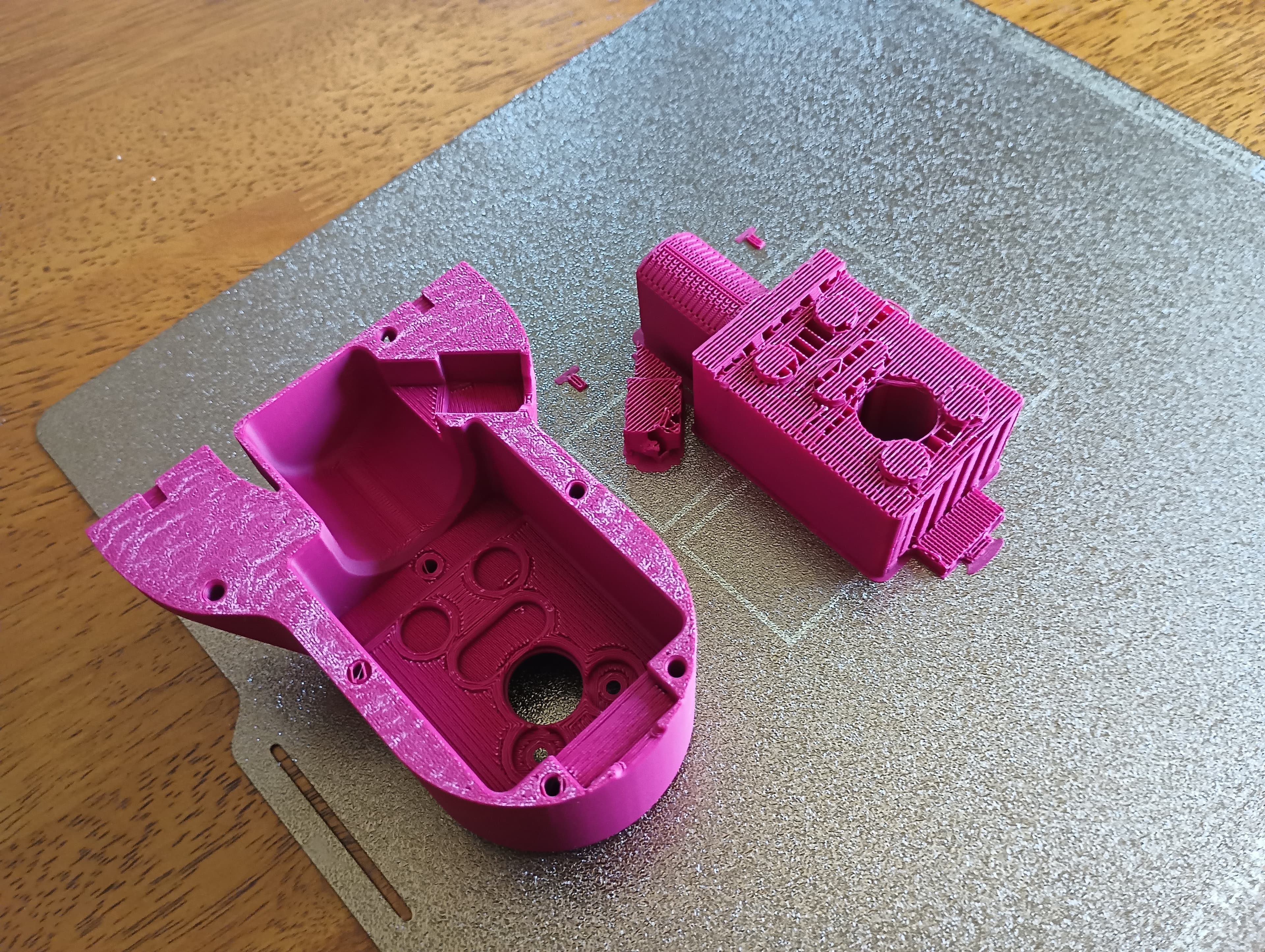
(Left) - freshly printed Pump Body (Right) - Pump Body cloeanly released from the build plate leaving only support material behind
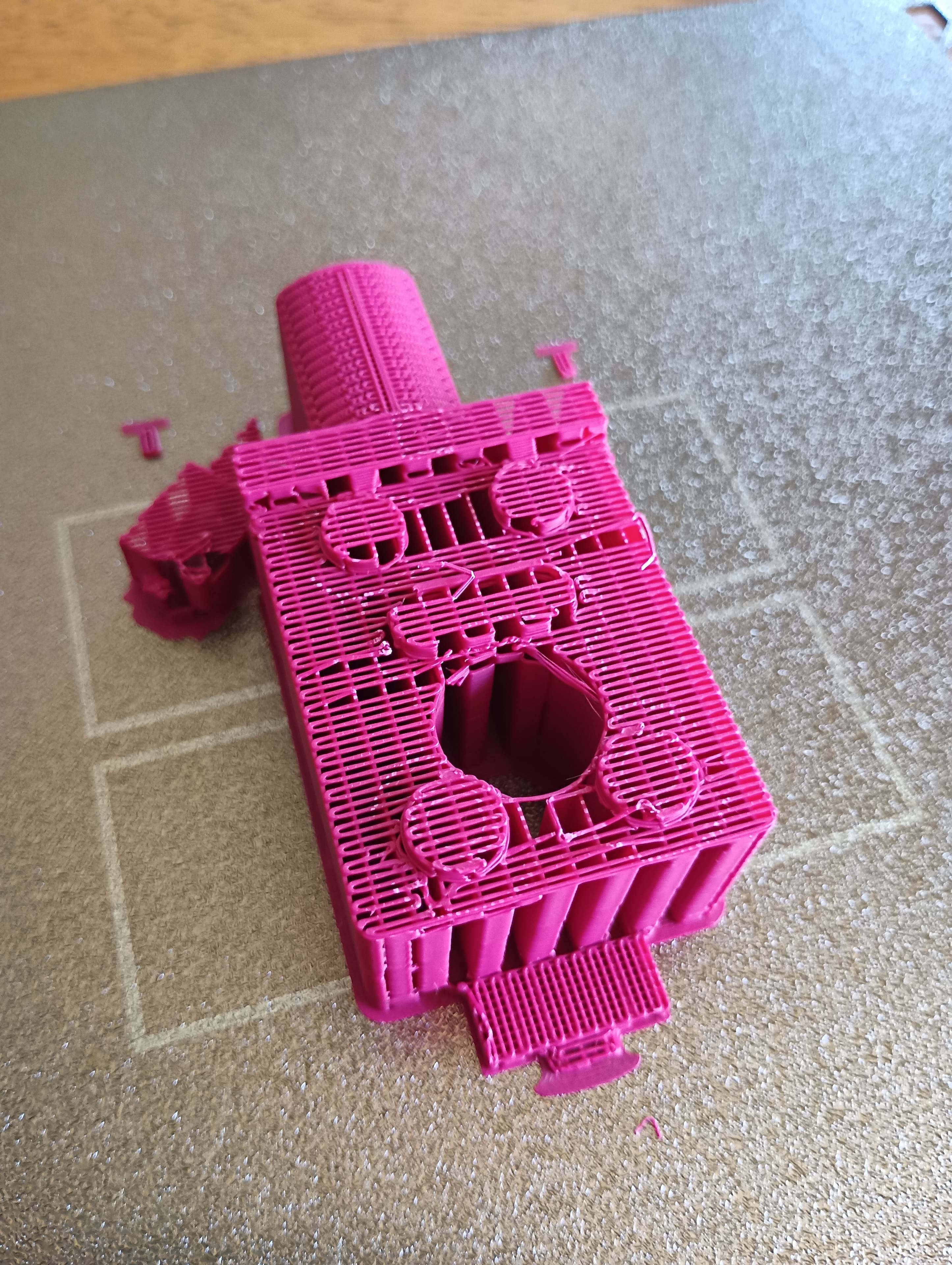
(Left) - support material only for inside of Pump Body (Right) - internal motor mount surface, after support removal
Print Post-Processing
-
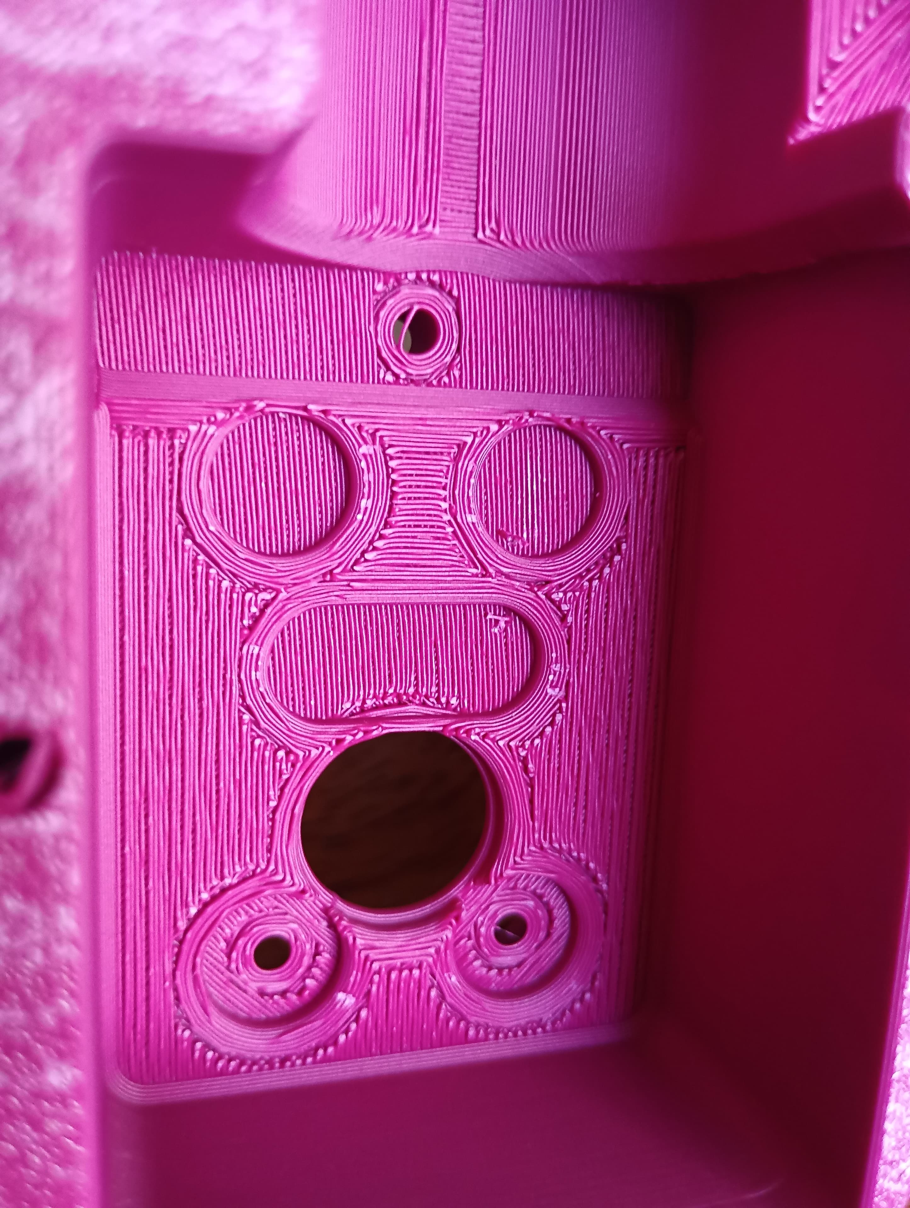
Once you have printed all your Pump parts, you will first need to carefully remove all the support material from the Pump body. You can do this with a flat-head screwdriver - being careful not to mar, scratch or dent your print. Its very important that you are thorough with this step, as any residual support material can cause assembly issues further down the line. Pay special attention to the marble input and output channels and also to the motor mounting surface inside the Pump body.
-
Next, you will need to install the 9x M2 Heatset inserts into your Pump Body, 6x in the rear for attaching the Pump Back and 3x in the front for attaching the Pump Ramp. Use a soldering iron set to about 300C or 575F to install the heatset inserts. Be attentive to installing them square to the Pump body for best fitment.
Wiring
Preparation
Before beginnning the wiring of you Marble Pump, you will need to do a few steps of preparation. The USB C PD Trigger board rests directly on the back of the DC Motor gearbox, and so the motor needs a layer of insulating Kapton tape to insulate it from the USB C Trigger PCB. Make sure to cover the entire back of the gearbox with Kapton tape as shown in the image on the left below.
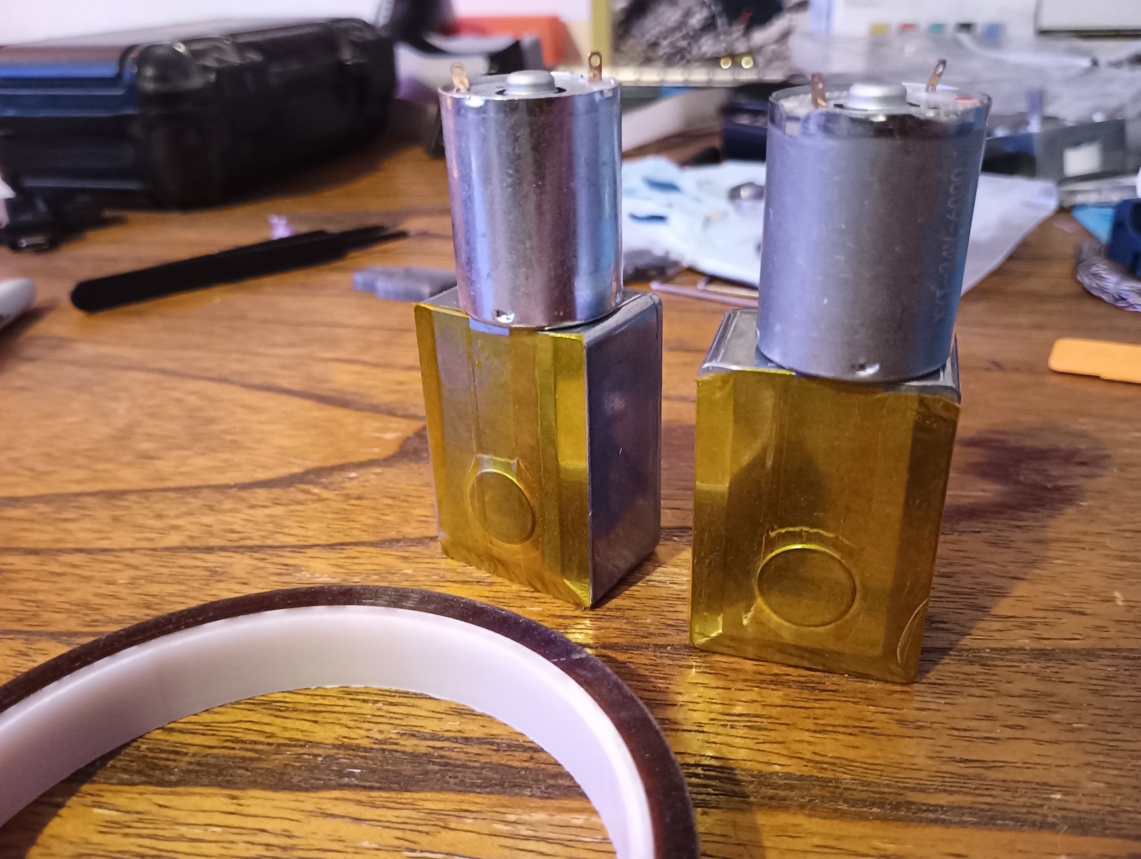
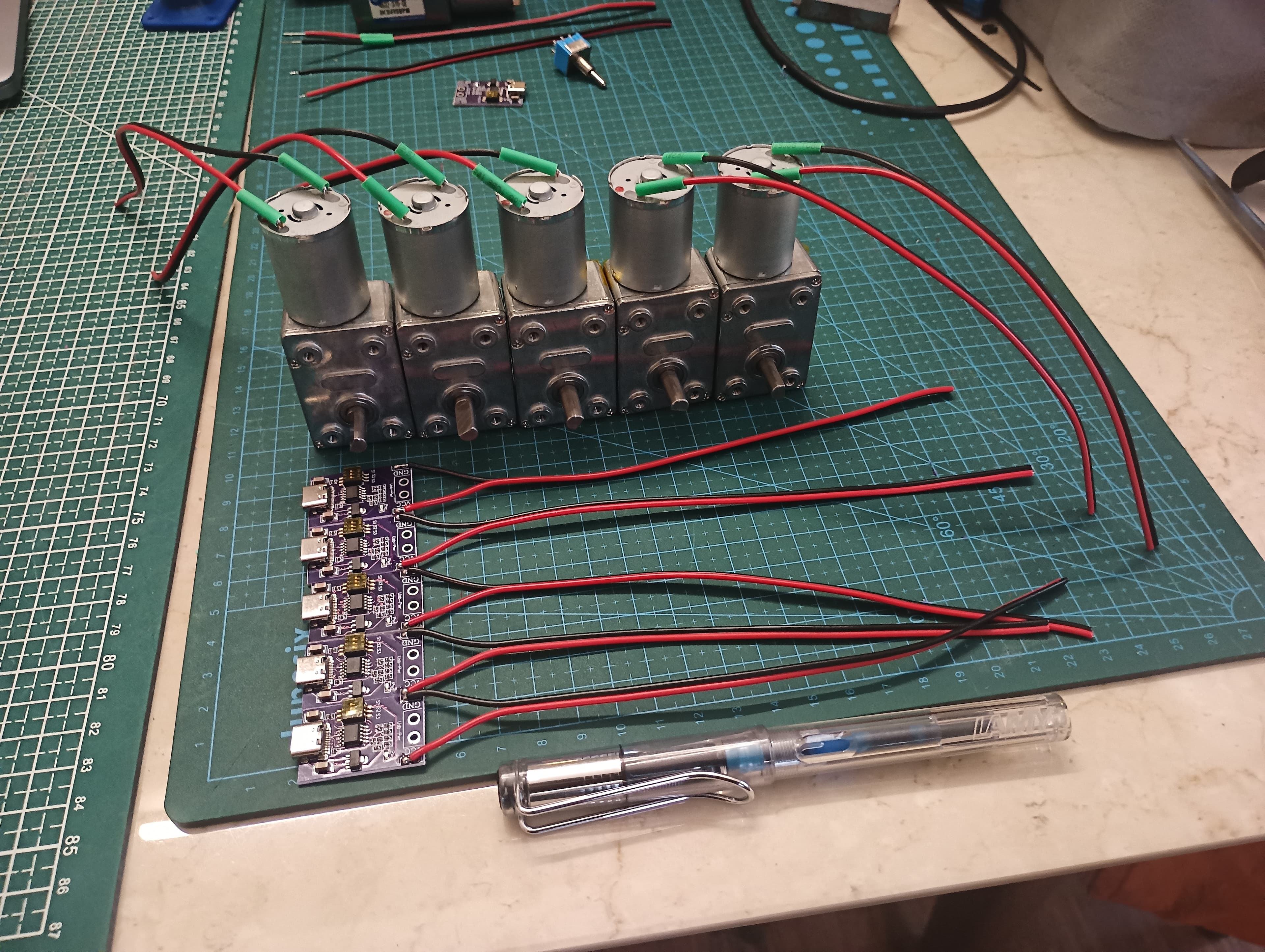
Once your motor body is insulated, go ahead and cut a piece of wire 200mm long, and strip both the red and black sides by 10mm. If you are using zip cord, split the wires 50mm. Then cut two 15mm lengths of heatshrink with an ID ~2.5mm and slip over each end BEFORE soldering them to the motor terminals. Solder the red wire to the terminal labelled "+" and solder the black wire to the terminal labelled "-" on the motor. After you are done soldering the motor wires on, heat the heatshrink tubing with a heat gun to shrink it down over the solder joint. When you are finished it should look like the motors in the image above and right.
Now its time to do a similar prep process for the wires on the USB Type C Trigger PCB. Cut another piece of wire 200mm in length and strip both the red and black sides by 3.5mm. If you are using zip cord, split the wires 40mm. Tin the stripped ends of the wire, as well as the + and - terminals on your USB C PD Trigger PCB. Solder the red wire to the terminal labelled "+" and solder the black wire to the terminal labelled "-" on the PCB. When you are finished it should like the PCBs in the image above and right.
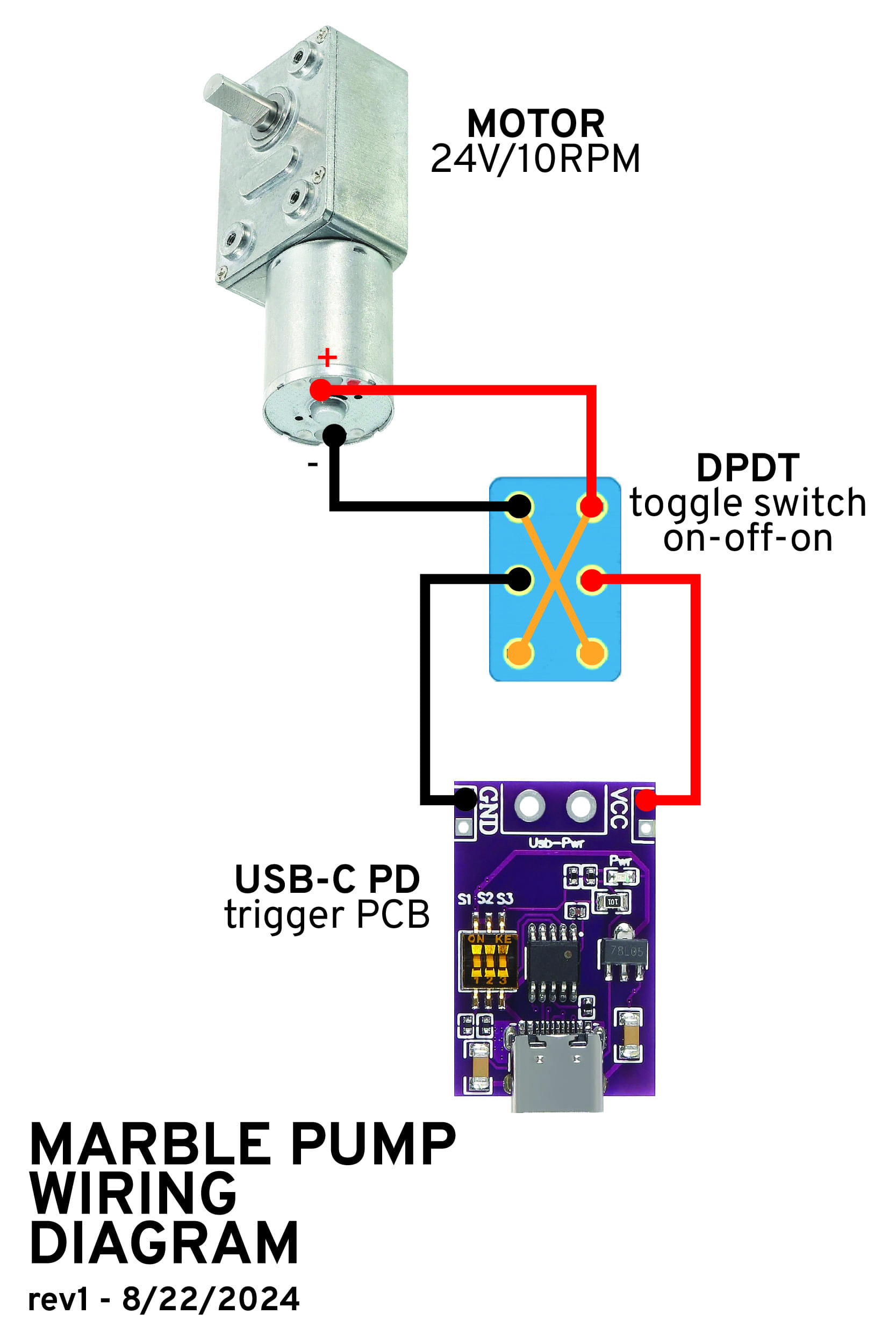
Wiring the H-Bridge
Wire the USB C PD Trigger board, toggle switch and DC motor as shown in the wiring diagram below. You will need two resistor legs to wire the crossed legs of the H-Bridge.
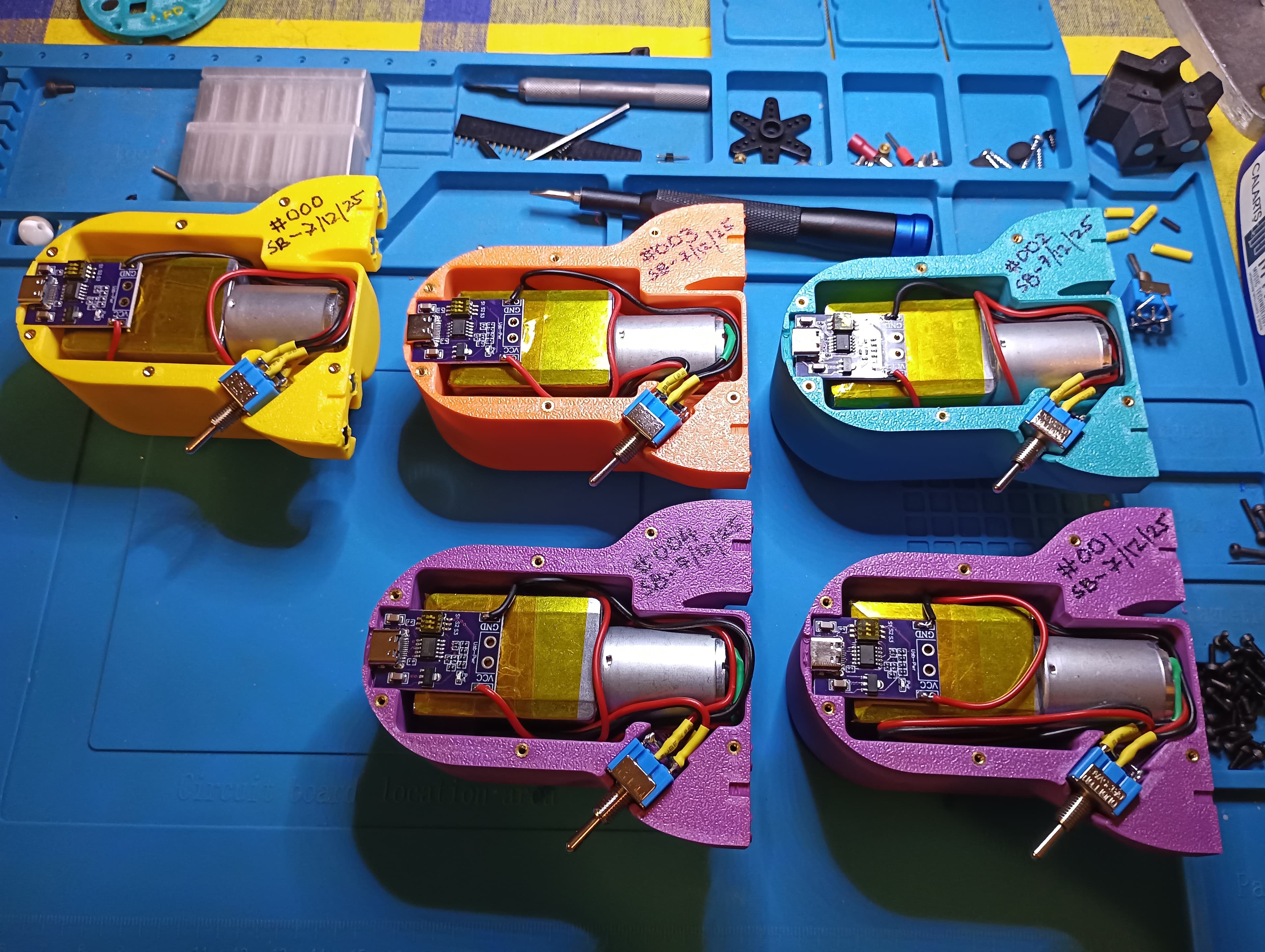
A finished batch of Marble Pumps waiting to have their Backs screwed on